DWMC-16: Initial 16 bit ALU and some Dark Register Magic - Deprecated
Now that I got some instruction set design done, I believe it is time to use the initial 4 bit ALU design and build up an initial full sized 16 bit ALU design. That means dealing with all the flags that can be set by the ALU, as well as dealing with the additional instructions that cannot be implemented in the hardware of the initial 4 bit sliced ALU.
Full Size 16 bit ALU
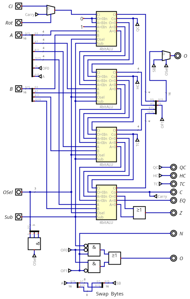
Of course in the simplest design, all I need is to chain four existing ALUs one after the other, followed by combining/splitting the 16 bit inputs into the 4 bit wide busses needed by the smaller ALUs. The carry bits of the individual 4 bit ALUs then become their own Flags, $ QC $ (quarter carry), $ HC $ (half carry), $ TC $(three quarter carry) and $ C $ (carry). Equally simple is the $ EQ $ (equal) flag, which is simply the $ A=B $ output from the last 4bit ALU. The $ N $ (negative) flag is simply the extension of the MSB (bit 15) of the output, indicating whether the number on the output is signed or not.
The $ Z $ (zero) flag is only a tiny bit more complex, simply combining the $ O=0 $ (Output equal to zero) and $ A=0 $ (A equal to zero) with an OR gate.
The $ O $ (overflow) flag is more complex, as there are three states when an overflow occurs during addition or subtraction. During addition, it happens when the MSB flips, either from 1 to 0 or from 0 to 1. During subtraction, an overflow occurs if the MSB flips from 1 to 0. The logic used is simply $ O = \overline{SubMSB[A]}MSB[O] \vee MSB[A]\overline{MSB[O]} $.
The new instruction of Logical Swap Byte lsb Rd is dealt with by the 'swap bytes' in the logical diagram. To select the operation, I am using the free operation in OSel at 0b111, which only needs a simple three input AND gate to select on the new multiplexer on the output.
Finally, we have the new Logical Rotate Left/Right lrl/lrr Rd. Here, I need to be able to slip the carry from the last 4 bit ALU into the first directly. This is achieved by the $ Rot $ input, which is set to high when lrl/lrr are executed. A multiplexer in the path ensures that $ Ci $ is only used when lrl/lrr are not executed.
Dark Register Magic
Something that came up in a discussion on Discord after my last post, was that the Flag register could be used to nondestructively test whether a bit it set or not. By going a push/pop of the Flag register to the stack before/after doing the testing instruction. I feel it would be a possibility, but it's a bit too dark of register magic for me. However, there is the potential to implement a pair of branch instructions to nondestructively check whether a bit is set inside a 16 bit word, operating on another register. The logic itself would just be a multiplexer operating on the Flag Register and the new register.
I decided it would be register R8. R8 was originally meant to be the number zero, but after some thinking, I came to the conclusion that the only place I needed the number zero, would be when I do increments or decrements. This means R8 would be a perfectly usable register, but it would still allow to run those tests on each bit.
New Register Layout
General Register Layout
| R00 | R01 | R02 | R03 | R04 | R05 | R06 | R07 |
|---|---|---|---|---|---|---|---|
| R08BT | R09F | R10PCL | R11PCH | R12SPL | R13SPH | R14ZL | R15ZH |
| Register | Register Label | |
|---|---|---|
| R08 | BT | Test Register |
| R09 | F | Flag Register |
| R11,R10 | PCH, PCL | Program Counter |
| R13,R12 | SPH, SPL | Stack Pointer |
| R15,R14 | ZH, ZL | Z Address Register |
New Conditional Branch Instructions
| Command | Mnemonic | Operation | Opcode | Affected Flags |
|---|---|---|---|---|
| Branch if Flag | bf F, Addr |
if (F == 0): PC <= Addr | 0b10000000/0x80 |
None |
| Branch if not Flag | bnf F, Addr |
if (F != 0): PC <= Addr | 0b10000001/0x81 |
None |
| Branch if Bit | bb B, Addr |
if (B == 0): PC <= Addr | 0b10000010/0x82 |
None |
| Branch if not Bit | bnb B, Addr |
if (B !=0): PC <= Addr | 0b10000011/0x83 |
None |
| Branch if Zero, Decrement | bzd Rd, Addr |
if (Rd == 0): PC <= Addr | ||
| else Rd <= Rd - 1 | 0b10000100/0x84 |
C, Z, N | ||
| Branch if not Zero, Decrement | bnzd Rd, Addr |
if (Rd != 0): PC <= Addr | ||
| else Rd <= Rd - 1 | 0b10000101/0x85 |
C, Z, N | ||
| Branch if Registers Equal | breq Rs, Rs2, Addr |
if (Rs == Rs2): PC <= Addr | 0b10000110/0x86 |
C, Z, N |
| Branch if Registers not Equal | brne Rs, Rs2, Addr |
if (Rs != Rs2): PC <= Addr | 0b10000111/0x87 |
C, Z, N |
| Branch if greater then | bgt Rs, Rs2, Addr |
if (Rs > Rs2): PC <= Addr | 0b10001001/0x88 |
C, Z, N |
| Branch if greater then or equal | bge Rs, Rs2, Addr |
if (Rs >= Rs2): PC <= Addr | 0b10001010/0x89 |
C, Z, N |
Conclusion
For the time being, I hope this will be everything I have to do to deal with the ALU and the instruction set. But knowing myself, I might come up with another idea or two to revise either. I certainly expect someone to come up and point me to an error. Though, this is generally an initial design and I will have to write a few tests to test both the 4bit ALU and the full 16 bit ALU in the logical circuit simulator software I am using.