DWMC-16 v2 Design Part 5b: Secondary Stack Pointers Addition
With the last Post, I decided that I would modify the system a little, with a modification to add nor three bit four Secondary Stack Pointers, simply by removing the PC Offset Register from the Special Registers. This does not however mean that I remove the relative jumps, those are dealt with separately.
Special Use Registers
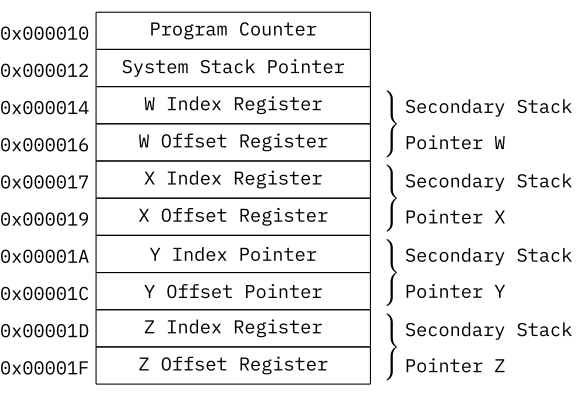
The Special Purpose Registers are a set of different registers that are used for special purposes by the CPU. Other than the General Purpose Registers, they cannot be directly accessed by the ALU or the control logic and are instead accessed via memory access in the memory area between 0x00010 and 0x0001F.
None Special Use Registers in Memory
Program Counter
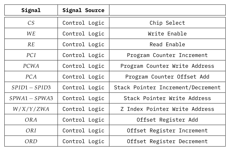
The Program Counter is a 20 bit register that contains the current address that is accessed by the CPU. The Program counter can be increased automatically by 1, 2 or 3. It can also be read and written to. Its control signals are $ PCI $, $ PCWA $, $ CS $, $ WE $ and $ RE $.
System Stack Pointer
The System Stack Pointer is a 20 bit register that contains the current address of the Systems Stack. The System Stack Pointer can be automatically increased and decreased by 1. It can also be read and written to. Its control signals are $ SPID1 - SPID3 $, $ SPWA1 - SPWA3 $, $ CS $, $ WE $ and $ RE $.
W/X/Y/Z Index Registers
The Index Pointers are 20 bit registers that contain a memory address that can be used by the CPU for indirect addressing of the main memory. It can be read and written to. Their control signals are $ W/X/Y/ZWA $, $ CS $, $ WE $ and $ RE $.
W/X/Y/Z Offset Registers
The Offset Registers are 16 bit registers that contain an offset that is automatically added to the corresponding Index Register when the appropriate memory addressing method is selected. Their control signals are $ CS $, $ WE $ and $ RE $. To add to their index registers, the control signal $ ORA $. The selection of the correct Offset Register is done by the $ W/X/Y/ZWA $ signals. Additionally, they can be automatically incremented and decremented by the $ ORI $ and $ ORD $ signals in combination with the $ W/X/Y/ZWA $ signals.
Secondary Stack Pointers W/X/Y/Z
The Index Registers and Offset Registers in combination can act as additional Secondary Stack Pointers.
Possible Implementation
Program Counter
Five 74191 synchronous presettable up/down 4-bit binary counter can be used to implement the Program Counter.
Stack Counters
Five 74191 synchronous presettable up/down 4-bit binary counter can be used to implement the Stack Pointers.
W/X/Z/Y Index Registers
Five 74373 octal latches can be used to implement an Index Register.
W/X/Y/Z Offset Registers
74191 synchronous presettable up/down 4-bit binary counter can be used to implement the Offset Registers, in combination with five 74283 4-bit binary full adders can be used, with a single 2:1 multiplexer to select between the adder and the Index Registers. This allows the use as Secondary Stack Pointers.
Memory Operations
The Memory Operations help define the different types of data access modes that will be used within the DWMC-16 Instruction Set by other operations, so the memory address modes will be defined in this subsection.
The general OpCode design has already been defined earlier and will be used here.
None Memory Modes
 Memory Operation OpCodes
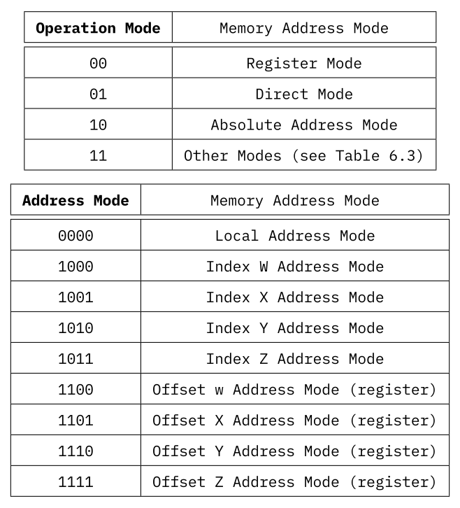
There are several different Address Modes encoded in the 2 bit Operation Mode and the four bit of the Control Code used by the 'Other Modes':
Register Mode
Register to Register Mode. This mode is not used by LD and ST, but almost exclusively by Arithmetic Logical Operations and Branch Operations.
Direct Mode
The Direct Mode loads the 16 bit value from the data word following the operation into the destination register.
Absolute Address Mode
This Mode uses the lower four bit [3:0] of the Control to encode the upper four bit [19:16] of the 20 bit address, while the data word following the operation encodes the lower 16 bit [15:0] of the 20 bit address. This allows to address the full memory space of the system.
Local Address Mode
The local address Mode allows to address only the local 64 kiWord address space, with the upper 4 bit [19:16] taken from the systems Program Counter.
Index W/X/Y/Z Address Mode
In this addressing mode, the system uses the content of the W/X/Y/Z Index Register to point towards a memory cell to read data.
Offset W/X/Y/Z Address Mode
Using this mode, the system is able to read from a list of data, relative to the address to the W/X/Y/Z Index Register, allowing access to lists/arrays of data. This can either be done by the register, or using a more direct method, where the command itself loads the data word following the operation directly into the W/X/Y/Z Offset Register.
Other Operations
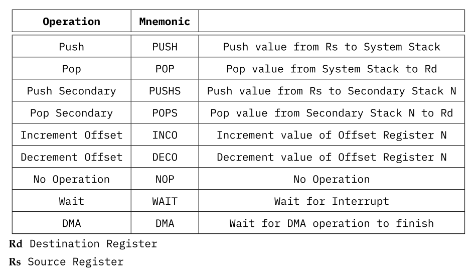
All operations that do not fit into the other three main types of operations, are listed in this section. None of these operations are making use of memory modes, but still are divided into two sub types.
None Other Operations
The OpCodes Layout of these operations are simplified, with six bit opcodes, the Operation Mode set to 00 and the Control Code either set to 00000000 or set to contain the Source/Destination Register and the System Stack used to contain the data. PUSH/POP and PUSHS/POPS are limited to the current Register Page and are not able to save any of the Special register to the selected Stack.
 OpCode Layouts for Other Operations
Memory Mode Mnemonics
Finally, there needs to be some thought put into the design of the Mnemonics used to designate the Memory Modes as defined under Data Transfer Operations for use in an Assembler program.
 Memory Mode Mnemonics